Chapter 9

ADVANCED SIMULATION USING ARENA

ARENA contains a range of features to support more advanced modelling concepts such as the ability to exchange data with other applications through data files, the possibiliy of aggregating a group of elements for part of the modelling cycle and the use of a range of conditional holds whereby an entity can be prevented from advancing through a model until a condition is met elsewhere in the model. Specific manufacturing features include materials handling capabilities in the form of transporters and conveyers. Whilst it is true that almost all of these objectives could be achieved with the elementary modelling constructs introduced in chapter 8 the use of these advanced features greatly simplifies the modelling process. This chapter introduces these more advanced features and then concludes with a brief overview of animation in ARENA.

9.1 Data I/O features and the TABLES element

Data is normally contained within the structure of the model either in the model blocks or the experiment elements. However there are many occassions when we wish to introduce data from an external source. For example the time of arrival of jobs to be processed in a flexible manufacturing cells may be contained in a production shedule which can be obtained from the companies database as a text file or the arrival of trains at a station may be obtained from a timetable. Similarly there are occassions on which it is useful to be able to record values generated in the model directly into a text file so that they can be analysed in another application. For example we may wish to record the costs of manufacturing each item (which may vary because of overtime payments etc.) so that the data can be exported to a spreadsheet used to estimate company cash flow requirements. The ‘READ’ and ‘WRITE’ blocks and the ‘FILES’ element are provided to support these modelling requirements.

9.1.1 The ‘FILES’ element

This element is provided to set up the basic information on a file used for data transfer. Table 9.1 identifies the information required.
Table 9.1
Operand Description Default value
Number File number sequential
Identifier File name used within ARENA by the READ and WRITE blocks blank
System name The name recognized by the computer system -
Access type Sequential, Direct(length) or User Sequential
Structure File structure : Unformatted, Free format, WKS or format (FORTRAN or C syntax) Unformatted
End of file action Error, Dispose, Rewind or Ignore Error

As usual with ARENA blocks you can ignore the file number and simply enter a file identifier. This is a name used internally within ARENA to identify the file. The system name is the name recognized by the computer operating system. For example within the model we may refer to the file by the identifier parts_data but this will be stored on the disk as C:\jan_data\parts.txt (System name). The system name must be enclosed in quotes.
The access type can be sequential in which each record in the file can only be accessed in sequential order (starting with the first) by a READ or WRITE block. Individual records can vary in length and so this file type represents the most efficient disk storage method because each record will only be long enough to contain the required data. Alternatively the access may be defined as direct (DIR for short) which allows direct access to any record or to a set of records in any order by READ and WRITE. This advantage comes at a price however because each record must be exactly the same length and that must be length of the largest record. In some circumstances this can lead to a considerable wastage of disk space. The length parameter specifies the exact size of each record in bytes.
The structure of the file refers to exactly how the data is stored on the disk. In some ways unformatted is the simplest (and incidentally the fastest to access) but its application is limited to exchanging data between different ARENA models or ARENA running on different hardware platforms. For example if you are modelling ‘Goods Arrival’ and ‘Goods Inspection’ departments of a warehouse you may need to build two separate models. The output of the ‘Goods Arrival’ model becomes the input for the ‘Goods Inspection’ model. Data can be stored in a disk file using the 'WRITE’ block in the first model and entered into the second model using the ‘READ’ block. Generally of more use are the alternative formats :

Free and fixed formatted records can be read and edited by text editors and accessed by a wide variety of applications.
When using the READ statement there is always the possibility of the model attempting to read data beyond the end of the file (See example 9.1 below) and the final operand informs the model how this situation is to be handled. The default situation is to generate an error and to halt the model. However it is possible, with a sequential file, to request the file pointer to be reset to the first record and to effectively rewind the file back to the start. Alternatively the arriving entity at the READ block may be destroyed or you can arrange for the READ instruction to be ignored.

9.1.2 The READ block

When a model entity passes a read block it triggers a read operation from a specified disk file. The requisite number of fields from the record is written into the appropriate entity attributes. The parameters of the read block are outlined in Table 9.2
Table 9.2 : The READ block
Operand Description Default
File_ID File to be read from (integer file number or name or STDIN) STDIN
Format File format (the same options as with the files element) Format specified in the FILES element or FREE for STDIN
Record number Record number to read Next record
Variables List of variables to read -

STDIN represents the standard input device which is normally the keyboard. If your model contains only a single READ block the it makes sense to define the file format within the block using the second parameter. However if you are using several READ blocks all with same format it is more efficient to use the FILES element. A format specification in the READ block always over writes that defined in FILES. The record number is only used for direct access files and is ignored with sequential files.

Example 9.1 The Bus Station

Buses arrive at a city bus station according to timetable. The buses will drop off passengers at one of three drop off bays before proceeding to their pick up bay when new passengers will board the bus. A text file has been created containing the bus number, arrival time and number of passengers as in the following example :
126 3 22
51 7 12
23 10 52
126 13 15
12 18 29

Thus, for example, we see that the bus number 126 arrives at 3 minutes and 13 minutes into the simulation and on the first occasion contains 22 passengers.
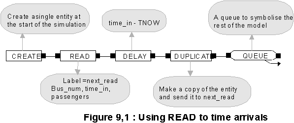
Let us assume that the text file has a disk file name of TIMETABLE.TXT and resides in the current directory. We will use Bus_in as the local identifier. The following ARENA model fragment will model the bus arrivals for us.


A single entity is initially created at the start of the simulation and is used to read the first record from the data file. A delay is then used to allow the entity forward at its correct arrival time. The entity is then duplicated (each copy has all the attribute values) and one copy proceeds to the rest of the model and the second copy returned to the READ block to activate the next read.
The associated FILES element contains the following information
Operand Default value
Number -
Identifier bus_in
System name TIMETABLE.TXT
Access type Sequential
Structure Free
End of file action Dispose

When an attempt is made to read beyond the end of the data file the entity is disposed and the read cycle of activity ceases.

9.1.3 The WRITE block

This block writes a record to a specified external file whenever an entity passes through the block. Its operation and set of parameters is very similar to the READ block.

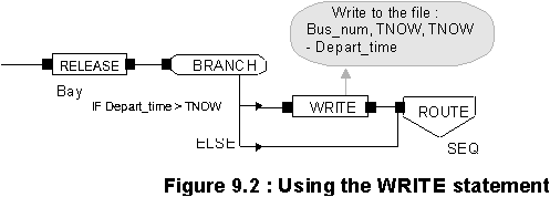
Example 9.2

When a bus leaves its pickup bay, if it late departing its service number, time of departure and number of minutes late is recorded in a disk file

9.1.4 The TABLES element

This element is provided in ARENA to give a table function capability to models. A table function is a relationship between two variables which is expressed as a table of corresponding values. For example we might need to model a situation when the time taken to drill through a metal block depends in a non linear fashion on the block thickness (perhaps because we need to allow extra cooling time for the drill bit). The associated table function might look like the following :
Block thickness (cms) Drill time (secs)
1 5
2 12
3 20
4 28
5 40

To specify a table function in ARENA you need to tell the TABLES element in addition to the table name, the least value of the independent variable (block thickness in our example), the constant increment in this value and finally a list of dependent variable values. Thus for the example above the data stream to be recorded in the element is :

Drill_time,1,1,5,12,20,28,40

To use the table data we would specify, for example, the delay representing drilling time as :

When, as in this example, the independent value (block thickness 4.3) is between table values ARENA will use linear interpolation to determine an approximation to the value required.

9.2 Station sub models

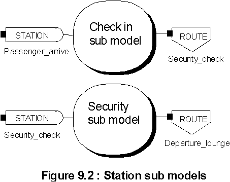
As the models that you build become more complex it can be more difficult to ensure the correctness of the model during verification and validation. Also on a large project it may be desirable to employ more than one modeler. An obvious way to control the development of a large scale modeling project is to divide the total model into a number of smaller models each of a more manageable size. Within ARENA the station sub model is the way to achieve this. Often the real problem divides up naturally into smaller components. For example a manufacturing plant may consist of a set of flexible manufacturing cells or an airport may be modelled as a check in area, a security zone and a departure lounge. The STATION and ROUTE blocks are usually the most effective way to link sub models together as indicated in Fig. 9.2

In simple models the sub models may only be connected via the ROUTE - STATION link but it is possible for them to be also connected in other ways. For example two sub models may share common resources.
An additional reason for using station sub models occurs when you need to model a group of identical or near identical sequences of operations. For example in building a model of a computer cable manufacturing company the following sequence of operations need to be modelled for each work centre : combine individual wires into bundles - sheath bundles in first envelope - add the screening braiding to the bundle - add outer sheathing and finally print cable identifier onto the outer sheath and wind onto drum. The company may have up to 100 such assembly stations within its manufacturing area. Each assembly station can be modelled using very few ARENA statements (see Worksheet XX) but it would be both wasteful and tedious to repeat this sequence up to 100 times. This problem can be solved using indexed resources and queues. Indexing of resources, queues, counters, tallies etc is achieved using the SETS element.

9.2.1 Indexing using the SETS element

The SETS element allows us to refer to a group of items using a common name. When correctly indexed, for example, we can refer to each member of a group of 10 queues with the common name of ‘Machine_buffer’ as Machine_buffer1, Machine_buffer2,........ Machine_buffer10 or in the alternative form Machine_buffer(1), Machine_buffer(2), ........ Machine_buffer(10).
The parameters required for the SETS element are given in Table 9.3
Table 9.3 : The SETS element
Operand Description Default
Set number Number which identifies the set sequential
Set name The name of the set -
Members List of members -

The list of members can be specified in a number of ways :